
We finally have two Cab Controlled working loops which have adhered to the guideline 'using what we already have' - and used a score of other parts we didn't.
For a beginner, I can only say the journey from design to track laying has been as much of a learning curve as creating the baseboard and design was.
Turns out, translating the design on to the baseboard is yet another, different, skill, requiring a great deal of patience and planning, and limited by some immoveable - seemingly obvious - practical constraints. For instance:
- fixed curves take up a fixed space
- a double track crossover ties those two tracks together and influences the spacing of everything attached to it - like a double loop
- placement of turnouts, especially when powered, is dependent on the construction of the baseboard
- available cash
As obvious as these constraints were, most of them weren't obvious to me as a beginner until I took to the board with track and track pins in hand.
Phases and Stages
- Phase 1: lay the double loops with crossovers, the Tennille/Sandersville interchange yard, and the RailInc. passing sidings/yard
- Phase 2: lay Sandersville
- Phase 3: have a cuppa
- Phase 4: play with trains
- some left over flexitrack
- the E-Z track curves for the loops
- some 3 amp wire
- one SL - 395 medium turnout
- trackbed
- six more turnouts
- more flexitrack
- track pins
- rail joiners (insulated and standard)
- a new soldering iron
- switches for Cab Control
- track cutters
- incline starters and risers
- some 3mm MDF for the raised section and to help raise the flexitrack to the level of the E-Z track (which stands about 5mm above the baseboard)

Laying Tennille Norfolk Southern Main and A/D Track - Or Phase One, Stage One

- Stage 1: lay the front part and temporary track for two loops
- Stage 2: install powered turnouts for the crossovers
- Stage 3: lay the curve inclines and track and raise the back, laying temporary track
- Stage 4: lay the RailInc. yard
- Stage 5: lay the Tennille-Sandersville interchange yard
To Twistlock or Not to Twistlock
I watched the sales video from Peco and then watched the bloke from Aber Halt Junction actually installing the motor and decided it was a go.
I approached the baseboard with something like trepidation, prepared to lay track, so much planning had all lead to this point in time and... realised two of the Twistlocks would be over baseboard supports...
This threw me for a few days as I mocked and re-mocked up the curves and turnouts.
Technically, the plan hadn't changed, but its placement on the board had, because of the placement needed to fit the turnout motors.
I decided that I would need to install at least one Twistlock before laying the straights, to get everything in a position where it would work - this included thinking about the RailInc. (rear) yard turnouts and the space needed for them, which had been shunted sideways along with everything else attached to the loops.
Fortunately, the local train shop guy at Iron Horse Hobbies instilled me with some regained confidence when he said that he'd used the PL-1000, that it was as easy as the Aber Halt Junction video and that he wouldn't be using anything else for turnout motors from now on.
I got home and approached the baseboard with even greater trepidation - had I got it right this time?
I laid the MDF and trackbed, waited for it to dry, positioned and repositioned the Twistlock motor template, then repositioned it again, raised the drill and...
...it was a really simple, easy, installation. A very good product that even a complete beginner like me can install - and I mounted it 'to the left' (reversing the template) to save space as the instructions offer.

With the initial placement of the loop finalised I set about laying track - finally.
Transitioning to/from E-Z Track
Having played around with test tracks and having polled the forums, I realised the Bachmann E-Z track sits quite high above the baseboard - approx. 5 - 6 mm. I needed to come up with a way of transitioning into flexitrack and peco turnouts from E-Z track.
At first I was just going to slice the connectors off the E-Z and use 1mm - 2mm shims to gently transition to the 3mm Woodland Scenics trackbed, as the forum guys seemed to indicate was the thing to do. But I decided that in the future, I may want to sell the E-Z track and slicing off the connectors would make it worthless.
I also had to take into account one of the guidelines for the layout, it had to be taken down and stored on its side in the garage. I decided that I'd make little dioramas using 3mm MDF as a base, that could be taken off the layout for storage. Track and 'flat terrain' (like grass) would stay in place but things like structures will be removed. As such, the non-E-Z track could be raised up without looking weird (because the surroundings would be raised about 3mm and the track would sit at about 6mm) and without slicing into the E-Z track.
So I went for forming the track bed around the connectors and some amateur attempts with a chisel have done the job.
First I drew around the connectors to form a template, taped the paper template down on the MDF (aka trackbed base), and chiseled away the unwanted MDF.
The transitions have worked well, although the MDF was variable in its thickness it turns out- one end was 4mm.
Now I can shape the bed once other yard track is in place and ready to be ballasted.
Mocking Up and Short Straights

I highly recommend beginners have a couple of sets of short straights at hand at all times for those situations where you go 'oh dear, that's not going to fit'.
In my case this was having to shorten the side straights in the fixed curves using 1.125'' rather than 2.25'' sections, included in Bachmann Assorted Straight Short Sections (N Scale) 44829, because the 'Twistlock incident'.
After that, I realised that fixed parallel curves act in a certain way and that, using the Peco N 6 foot gauge as a minimum, I could in fact make the straights in the inside curves slightly longer than the outside without risking rolling stock and locos of passing trains, side swiping each other on the curves.
I also admit to caving in to the amateur 'cram as much track into the loops as feasibly possible' trick, but mocking up and short straights have made this possible.
Carving Up Your Precious Track - Using Peco Streamline Turnouts
During mocking up, I also realised that working with Peco Streamline turnouts means having to carve up track to make it fit.
For experienced railroaders I guess its nothing new, but to a beginner, I nearly had a heart attack when I realised I had to cut into the plastic ties!
But polling the forums via Mr Google confirmed that it is indeed what's needed. You have to slice away ties to make track fit around Streamline turnouts. Followed by even better advice, if at all possible, do not slice into the ties on the turnouts (for fear of the TOs going out of gauge), use straight sections of track and slice into them.

The red circles show where the trims were made on the straight (blue) track and I avoided trimming back past the little false-nails-clippy-thingies that hold the track in gauge, so that the track held in gauge.
Electrics
I am the destroyer of soldering irons.
About twenty years ago, to clean my soldering iron, I filed the tip and kept on using it. The resulting bright orange glow that developed from the tip and the iron was alarming.
More recently I totalled the tip on my new iron by wiping it on a sponge, without first wetting the sponge. Its totalled. Blackened, pitted, an ex-tip.
I suck at soldering. I think I did two reasonable solders before killing the tip... its gone, its shuffled off 'is mortal coil, run down the curtain and joined the bleedin' choir invisible.
But, and some would say its a big one, I persevered and soldered up all loop blocks without melting the ties or forcing the track out of gauge, or burning the house down.

Earlier in the the game I had added a new guideline to the list of guidelines for the railroad, minimal soldering and simple electronics.
Following the 'using what I had' guideline entailed using the two analogue controllers.
I'd decided on Cab Control and isolated sections during design, then adding the new guideline, I decided on Common Rail wiring and Atlas #215 Selectors to reduce the amount of wiring and soldering or "Keep it Simple Stupid".

Using KISS as a guideline, I connected up the common wires to a common rail bus, connected some to the track and connected the 'powered' wires for each block, turned everything on, flicked some switches and hey presto, dual cab, block control.
Trains seemed to lose juice on one section but that was as easy to fix as adding a wire to the common rail bus and the section, and hey presto again, juice fixed.
Tripping the Double Loop Fantastic

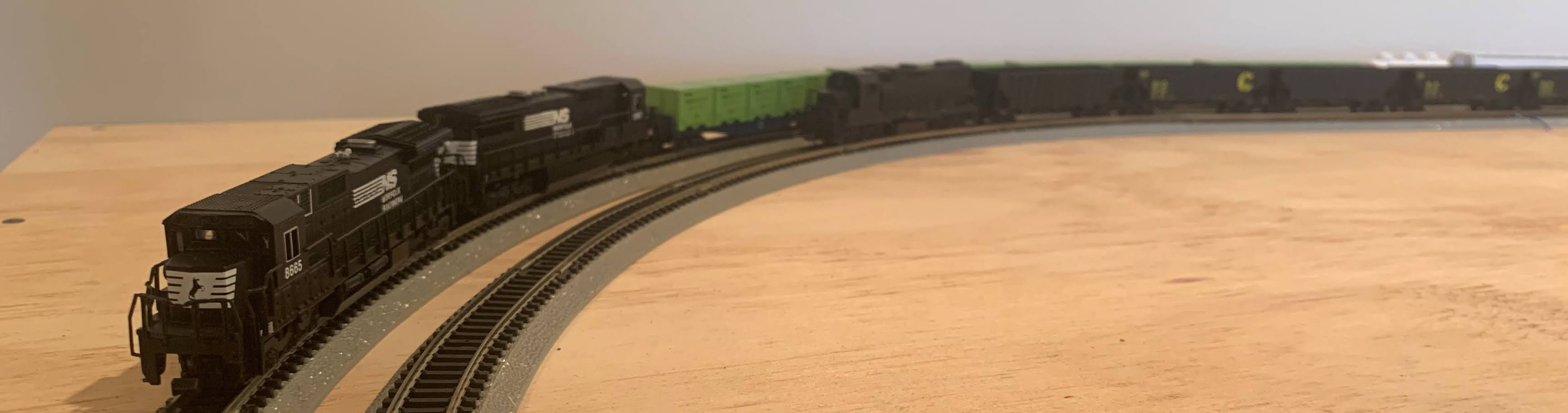
Although we are a long way off from 'permanently' finishing the Norfolk Southern portion of the railroad with anything like prototype operations, and although its been twenty years since I first dreamed of running two locos on the same track, we now have two operational loops.
But its been worth it. When my step-son saw two trains going around the loops, there was a genuine 'this is so cool!', followed the next day, when he got home from school and asked "Can I play with the trains?"
You know what little buddy, yes, you can finally play with the trains.
Job done.


No comments:
Post a Comment